In the Best Community Project category
General Arrangement Drawings
The Francis Turbine
The Francis turbine is a type of water turbine that was developed by James B. Francis in Lowell, Massachusetts.[1] It is an inward-flow reaction turbine that combines radial and axial flow concepts.
Francis turbines are the most common water turbine in use today and are primarily used for electrical power production. The electric generators which most often use this type of turbine have a power output which ranges from just a few kilowatts up to 800 MW. The speed range of the turbine is from 75 to 1000 rpm, the one at Harlaw runs at 750 rpm. Guide vanes around the outside of the turbine’s rotating runner control the rate of water flow through the turbine for different power production rates. Francis turbines are almost always mounted with the shaft vertical to isolate water from the generator. This also facilitates installation and maintenance.
A Francis turbine consists of the following main parts:
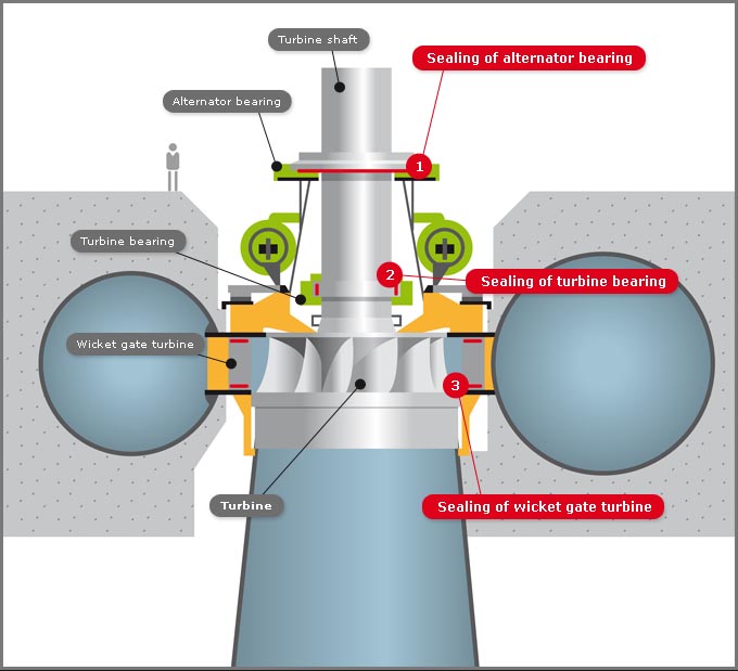
A Vertical Francis Turbine
Spiral casing: The spiral casing around the runner of the turbine is known as the volute casing or scroll case. Throughout its length, it has numerous openings at regular intervals to allow the working fluid to impinge on the blades of the runner. These openings convert the pressure energy of the fluid into momentum energy just before the fluid impinges on the blades. This maintains a constant flow rate despite the fact that numerous openings have been provided for the fluid to enter the blades, as the cross-sectional area of this casing decreases uniformly along the circumference.
Guide or stay vanes: The primary function of the guide or stay vanes is to convert the pressure energy of the fluid into the momentum energy. It also serves to direct the flow at design angles to the runner blades.
Runner blades:Runner blades are the heart of any turbine. These are the centers where the fluid strikes and the tangential force of the impact causes the shaft of the turbine to rotate, producing torque. Close attention in design of blade angles at inlet and outlet is necessary, as these are major parameters affecting power production.
Draft tube: The draft tube is a conduit which connects the runner exit to the tail race where the water is discharged from the turbine. Its primary function is to reduce the velocity of discharged water to minimize the loss of kinetic energy at the outlet. This permits the turbine to be set above the tail water without appreciable drop of available head.